
Description

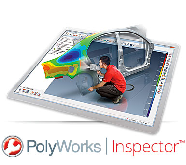
The industry-standard 3D metrology toolbox for product engineering, assembly guidance, and final inspection
PolyWorks|Inspector is a powerful industrial 3D metrology software solution to control tool or part dimensions, diagnose and prevent manufacturing and assembly issues, guide assembly building through real-time measurements, and oversee the quality of assembled products by using non-contact point cloud digitizers and single-point contact-based probing devices.

Align
Get the alignment right
Inspecting and analyzing a measured part is only possible if the digitized data is properly positioned and oriented in 3D. Typically, a measured part is aligned to its nominal CAD model to enable the extraction and comparison of nominal and measured dimensions. It can also be assembled virtually to the surrounding mating parts in order to check for interference issues or to analyze flush and gap deviations.
PolyWorks|Inspector offers a broad range of part alignment techniques that let users construct alignments with:
- Surfaces or cross-sections (measured-to-nominal best-fit, constrainable in rotation/translation, and within tolerance zone)
- Features (3-2-1, pairs of center points, and GD&T datum reference frames)
- Reference points and lines (RPS, surface points, and six-point nest)
- Virtual gauges (caliper, flush & gap, and airfoil)

Measure
Extract all required dimensions
At the core of the PolyWorks|Inspector workflow is the extraction of measured part dimensions and computing the deviations to their corresponding nominal dimensions. Thanks to the remarkable flexibility integrated into PolyWorks, dimensions can be extracted from measured point clouds, polygonal models built from point clouds, or probed points. Nominal dimensions can also be extracted from a CAD model or a reference measured part.
PolyWorks|Inspector delivers the complete toolbox you need to extract and analyze:
- Surface, boundary, and cross-sectional measured-to-nominal deviations
- Feature dimensions and GD&T controls (ASME Y14.5-2009 and ISO 1101, as well as PTB certified 64-bit/32-bit)
- Advanced dimensions such as flush and gap, profile radius, airfoil dimensions (leading edge, trailing edge, and global), assembly clearance, thickness, and more
PolyWorks|Inspector also offers real-time guidance to accurately build and inspect fixtures and jigs using single-point measurement devices.

Report
Generate updateable reports
PolyWorks|Inspector provides an outstanding updateable reporting technology that guarantees the exactness of a report and dramatically accelerates multipiece inspection.
Report items, such as 3D scene screenshots and result tables, are automatically updated if a project is altered. You can modify the parameters of a project, or replace the measured data points of the current piece by the data points from a new piece, knowing that the entire inspection report will automatically be updated.
Share inspection results
The PolyWorks|Viewer enables your colleagues, managers, and suppliers to review your inspection projects in 3D.
Key Technologies

Universal 3D metrology architecture
The relational, object-oriented, and parametric architecture of PolyWorks® allows the integration of all manually-operated and numerically-controlled point cloud digitizing and single-point probing 3D measurement technologies within a common framework, opening a new era of universal inspection projects and device interoperability.

Real-time quality meshing
The real-time quality meshing technology transforms laser scanning into a systematic and objective metrology process by creating polygonal models of digitized parts in real time and computing and displaying quality metrics that reveal ineffective scanning methods, allowing operators to improve the quality and precision of the measured surfaces and ensuring measurement repeatability.

Automatic updates of inspection projects
Thanks to the built-in traceability of the PolyWorks parametric architecture, users have the outstanding ability of modifying an object parameter, replacing an object, or changing the spatial relationship between two objects, and these changes will automatically be propagated to all the project’s 3D geometry and inspection reports to make them up to date, saving time and avoiding costly mistakes.

Play Inspection multipiece measurement tool
The Play Inspection tool marks the end of time-consuming teaching modes, as it dramatically simplifies the measurement of multiple pieces by automatically building, in real time, a guided step-by-step sequence to capture 3D datasets of a new piece, using point cloud digitizers and single-point probing devices.

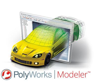
The modeling and reverse-engineering solution that enables true interoperability between digitized polygonal models and CAD/CAM applications
PolyWorks|Modeler is a comprehensive reverse-engineering software solution that allows extracting optimal CAD entities—curves, surfaces, parametric sketches, and prismatic features—from polygonal models of digitized parts to serve as the starting point in your professional CAD modeling solution.
Polygonal Modeling
Manufacture from polygonal models
The first step in a reverse-engineering workflow consists in transforming digitized point clouds into a polygonal model, an operation also called “meshing”. Sophisticated data-processing techniques, including point smoothing and curvature-based sampling, can be applied to raw point clouds during the meshing phase. As a result, polygonal models tend to be more compact, more accurate, and less noisy in comparison to the raw measurements.
Several industrial applications are capable of directly handling polygonal model representations. For example, polygonal models can be either directly milled, built using a 3D printer, or input into aerodynamic simulation software. PolyWorks|Modeler provides two categories of polygon-editing tools to prepare polygonal models for these applications:
- A first set of tools is designed to repair and optimize imperfectly digitized geometry. For example, it may be necessary to interpolate new polygons over unmeasured areas to create a complete surface representation.
- A second set of tools offers CAD operations on polygonal models, such as extrusion, offset, fillet, and Boolean operations.

Surface Modeling
Generate CAD-friendly freeform surfaces
Professional CAD/CAM solutions do not typically offer 3D modeling tools for polygonal models. One common way to transfer the surface of a digitized object into CAD/CAM software consists in fitting a network of NURBS surfaces over a polygonal model built from digitized point clouds. NURBS surfaces are ideal to mathematically describe freeform surfaces, plus they are CAD/CAM friendly.
PolyWorks|Modeler offers an intuitive surfacing approach in which curves are first laid down on a polygonal model, and then automatically intersected to form four-sided or N-sided trimmed NURBS patches. Next, the NURBS patches are used to control the fitting of a continuous network of NURBS surfaces. Fitted surfaces can then be exported to IGES or STEP files and directly imported into your favorite CAD/CAM application for further processing.
PolyWorks|Modeler’s NURBS surfacing technology offers a remarkable balance between lead time and surface quality, thanks to:
- Intuitive curve reshaping methods and curvature-continuous curves
- The best NURBS surface-fitting engine on the reverse-engineering market in terms of quality (accuracy, smoothness, and continuity) and flexibility (trimmed surfaces and T-junctions, curvature-based two-step fitting process, and the possibility of blending fitted surfaces to an existing CAD model for local CAD reconstruction purposes)
- G2-, G1-, or G0-continuity control over NURBS patch boundaries
- Automatic G2 surface fitting in areas where NURBS patches have a rectangular topology

Solid Modeling
Build solid CAD models from optimized geometric entities
The solid modeling philosophy of PolyWorks|Modeler consists in optimizing the extraction of geometric entities on digitized polygonal models, and then transferring these entities to your corporate feature-based solid CAD modeler to guarantee the creation of parametric, associative, and fully editable solid models.
A fundamental building block in a solid modeling workflow is the parametric 2D sketch. 2D sketches consist in planar entities, such as arcs, lines, circles, and splines, defined on a plane embedded in 3D space. In solid-modeling software, sketches are used to create solid base features by performing Extrude, Revolve, Sweep, and Loft operations. Sketches are created by:
- Defining a sketch plane
- Computing a sketch outline by slicing cross-sections of the digitized model or extracting its silhouette edge
- Anchoring and fitting sketch entities and dimensions, guided by the sketch outline
The parametric sketches are then transferred to the solid CAD modeler by using add-ins (for CATIA, NX, Creo, SolidWorks, and Inventor) or a neutral format (IGES). You can then combine the sketches and fitted NURBS surfaces, use the dimensions from fitted prismatic geometry, and design the solid model you want—all done directly in the professional CAD solution that you’re most familiar with. The solid modeling possibilities are unlimited with PolyWorks|Modeler, so let your creativity lead the way!

The mobile app that boosts measurement productivity on the shop floor
A single measurement specialist performs a measurement task that normally requires two people. An operator measures a part twice as fast by eliminating back-and-forth trips to the computer running PolyWorks. These are just a couple of examples of the outstanding productivity gains that the free PolyWorks|Talisman mobile app generates.

Control Remotely
Bring PolyWorks into the palm of your hand
The PolyWorks|Talisman app runs on mobile computing devices and communicates with PolyWorks through a Wi-Fi connection. A major benefit of the app is its capability to remotely control PolyWorks. While being in front of their part, operators can directly connect to their probing or laser-scanning device, configure measurement modes and parameters, launch a probing operation, and perform typical probing actions, such as measuring a point, ending object probing, deleting the last probed point, or reprobing an object.

Stay Connected
Get live feedback, anywhere
PolyWorks|Talisman also provides remarkable feedback on the PolyWorks measurement session in real time, such as:
- 3D Scene display, along with critical measurement information, such as guiding instructions, guiding images, guiding points, point counters for object probing, and more
- Single or multiple Digital Readout display to efficiently build fixtures and jigs
- Audio feedback to hear the sounds of the probing and scanning session
PolyWorks|Talisman also allows users to read messages and answer questions directly.

Enjoy Peace of Mind
Total confidentiality guaranteed
PolyWorks|Talisman is designed to guarantee total confidentiality under all circumstances:
- No proprietary information saved on the mobile device
- Encrypted communication
- No connection to Internet or any other computer
- Possibility to explicitly restrict usage to a predefined list of mobile device IDs
PolyWorks|Talisman offers ultimate security characteristics required for ultraconfidential setups.

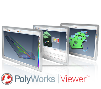
The effective solution to deliver metrology results in 3D to everyone in the organization
While engineering a new product or managing a manufacturing process, having access to 3D measurements and geometric analyses of parts, tools, assemblies, or products can be critical to making the right decision. Thanks to InnovMetric’s free PolyWorks|Viewer, 3D measurement specialists can share their PolyWorks|Inspector projects across the organization, allowing team members to extract the information they need from the measurement database.

Review
Quickly evaluate measurement results
The PolyWorks|Viewer solution allows everyone in the organization to quickly review the contents of a PolyWorks|Inspector metrology project. Thanks to a contextual project navigation toolbar, colleagues unfamiliar with PolyWorks can easily select individual pieces from a multi-piece project, measurement object categories (Data Color Maps, Features, and so on), and individual objects within a category to view them in 3D. Also, the formatted analysis reports produced by the metrology team are accessible directly from the navigation toolbar. PolyWorks|Viewer makes it easy for industrial manufacturing organizations to distribute metrology results to all the decision makers who need to access critical geometric data.

Analyze
Build your own view of the measurement database
PolyWorks|Viewer goes beyond its primary project reviewing functionality by offering the capability of extracting and reporting dimensional information that was not part of the original measurement plan. Using the Geometry Controls interface, users can control new dimensions and set up custom tolerances. The Data color map display can be fully customized and additional point annotations can be picked to highlight local deviations. For multipiece projects, users have access to the complete PolyWorks|Inspector SPC analysis toolset for object controls and surface Data objects. Finally, PolyWorks|Viewer allows users to create new report tables, object annotations, snapshots, and formatted reports. With PolyWorks|Viewer, everyone can build their own view of the measurement database.


Reviews
There are no reviews yet.