Description
Hull Structure Design
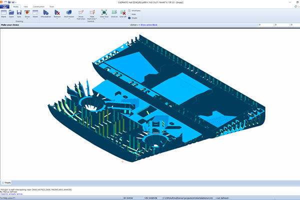
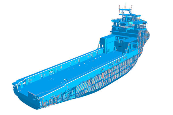
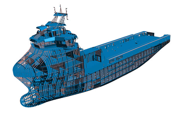
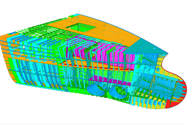
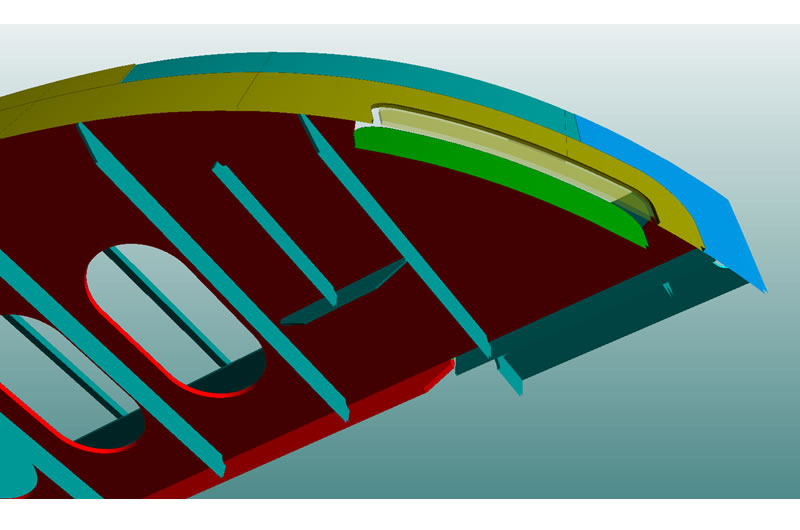
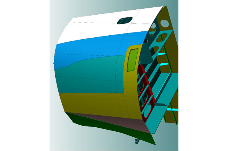
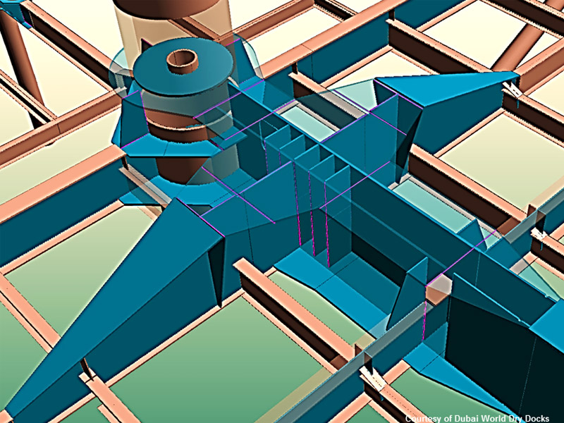
The Hull Structure module is the core of the CADMATIC Hull system. It is used for 3D modelling of the entire hull structure from basic design up to detailed design and production engineering of hull blocks, assemblies, panels and parts.
- Extremely fast and easy to use compared to other CAD/CAE/CAM systems
- Hull structures are stored topologically making modifications quick and easy
- The intuitive user interface guides the hull designer with maximum assistance while creating structural components
- Rule-based engineering assists the engineer and avoids errors
- Includes powerful copy functions, parametric definition of yard standards and many automatic mechanisms
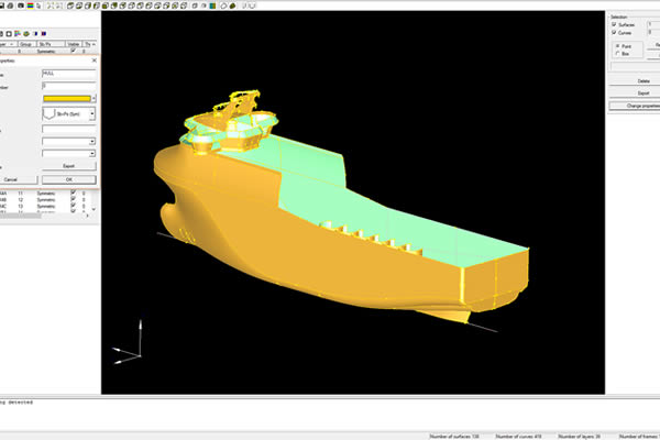
Hull Structure offers topology that supports and eases the designer’s work throughout the entire design process. Hull Structure also offers a specific and dedicated 2D drafting functionality to create and maintain general drawings and plans, whilst the Hull Shape Import Manager module makes it possible to import surface based hull shape models directly into CADMATIC, based on different independent file formats. The add-on module Shell Development and the Interoperability modules are also part of the Hull Structure Design sys-tem, and are licensed separately.
Shell Plates Development
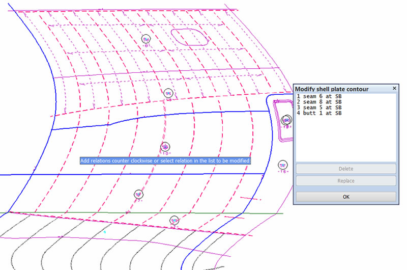
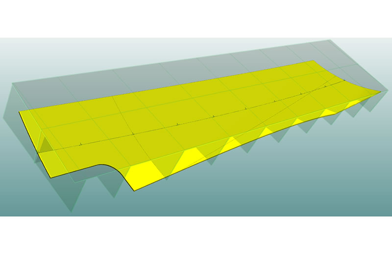
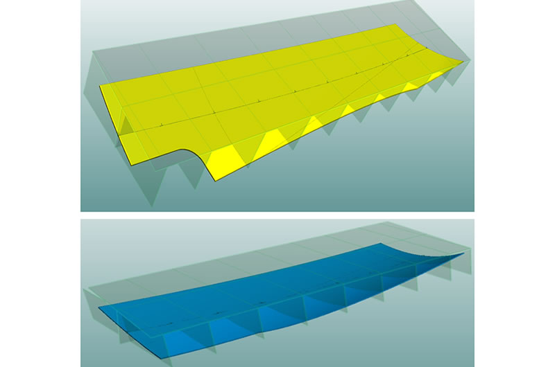
CADMATIC Shell Plates Development is a unique module for developing shell plates extremely accurately. It is suitable for both cold forming and line heating processes. The module mathematically calculates double curved plates into a flat pattern, taking care of the required elongation/shrink caused by the double curvature. Due to the accurate computation shell plates can be developed without green/extra length. The Shell Plate development module is an add-on module to Hull Structure Design.
- A powerful module for developing shell plates easy and extremely accurately
- Calculates templates for bending, including marking lines
- Generates elongation lists, 2D sketches and geometry of each shell plate ready for nesting
- Generates shell view drawings including aft, side, top and spatial views
The engineer has the possibility to add and modify topological seams & butts and other hull lines to the shape database with various functions, which offers a flexible way of working. 2D shell views can be generated automatically including seams & butts with the existing hull structure in the 3D hull model such as decks, girders, frames, etc.
The Pin-Jigs module creates pin-jig information automatically from the 3D model for larger shell plate panels and calculates the optimized position of the pin-jig. The Pin-Jigs module is an extra add-on module to the Hull Structure module.
Plate Nesting
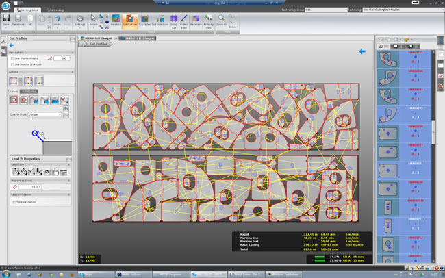
The CADMATIC Plate Nesting module is used to nest part geometries fully automatically and to optimize the use of raw plate materials to minimize material waste.
- Can be used in interactive mode, automatic nesting mode or a combination of the two modes
- Bridges, lead-in and lead-out, start holes, marking, text, bevels, net. weights, cutting lengths, rapid movement and time estimates are all included
- The module outputs nesting sketches, optimized NC code and nest reports for the workshop
- Includes ”smart” remnant handling and automatic grouping of parts
- Supports flame, plasma and laser cutting machines
The CADMATIC Plate Nesting module processes the CADMATIC Hull part geometries directly, but also accepts part geometries from other systems in standard DXF file format. The Plate Nesting module offers functionality for creating/modifying part geometries, remnant handling, automatic cutting path creation and generating the NC code for cutting machines.
Optional features for the CADMATIC Nesting module are Advanced Autonesting, Bevel-3: bevel cutting with a 3-torch flame cutting head, Bevel-1: bevel cutting with a single torch plasma head and Text Marking: marking text with inkjet and similar devices.
Production Information Hull
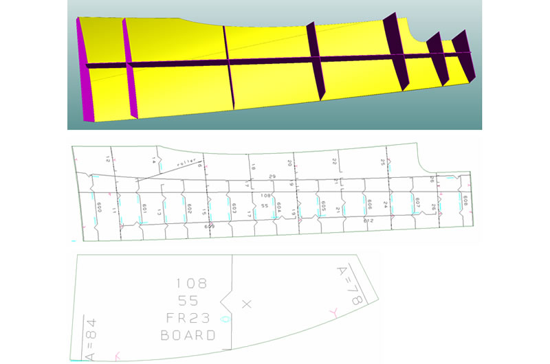
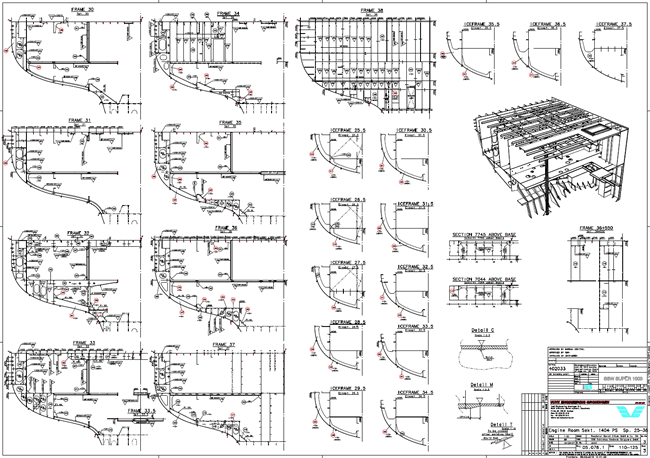
For production engineering a fully equipped set of work preparation tools is embedded in the CADMATIC Hull Structure module to ensure that the production department receives all the required information, such as part geometries, weld and bevel details, part lists, weights and CoG, profile lists, profile nesting, profile sketches etc. In addition it contains various build strategy features offering a wide range of possibilities to generate 2D and 3D work breakdown information and sketches.
- Production Information is directly derived from the 3D-model and therefore always up to date
- Enables users to define their own report layouts and logistic data fields required by the shipyard
- A build-in report generator enables creating of any kind of report by querying the 3D model for different production and logistic data
- Generates 3D work breakdown sketches and 2D+3D combination sketches and offers automated part numbering
- Visualize and simulate the build strategy of blocks, assemblies, subassemblies and panels
- Easy manipulation of the work breakdown structure by dragging and dropping parts in the tree structure
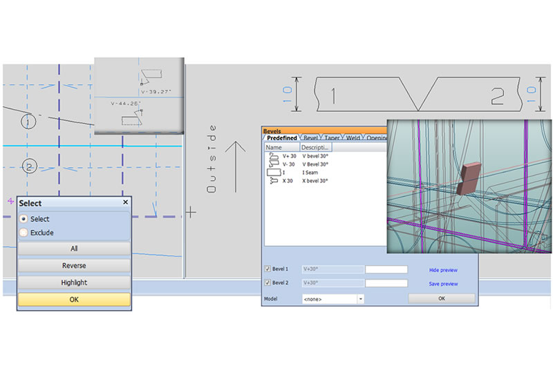
- Includes welding and bevel management functions, including reports
- Includes functions to control profile cutting robots of various suppliers
The Production Information tools streamline the information flow between, engineering, planning, work preparation and the workshop. This speeds up the process of work preparation significantly and thereby shortens the throughput of the ships’ assembly stages.
Marine Diagram, P&IDs
The CADMATIC Diagram module for flow diagrams, P&IDs and cabling diagrams is fully integrated with the 3D model. It provides the user with easy-to-use and efficient tools to create, modify and manage all kinds of diagrams.
- Flow diagrams, P&IDs, cabling diagrams
- Easy-to-use efficient tools to create and edit
- Concurrent multiuser/multisite environment
- Full integration with 3D model
- High degree integration with AutoCAD
Intelligent symbols, unlimited size of process lines, control of revisions and advanced database management with user-definable report generator are just some of the features of the Diagram module. Documentation for different piping and instrumentation diagrams, equipment lists, pipeline lists, and valve lists etc. can be automatically produced. Diagram can be used independently or with the 3D Outfitting Design seat and can be interfaced with different calculation software packages.
Outfitting Design
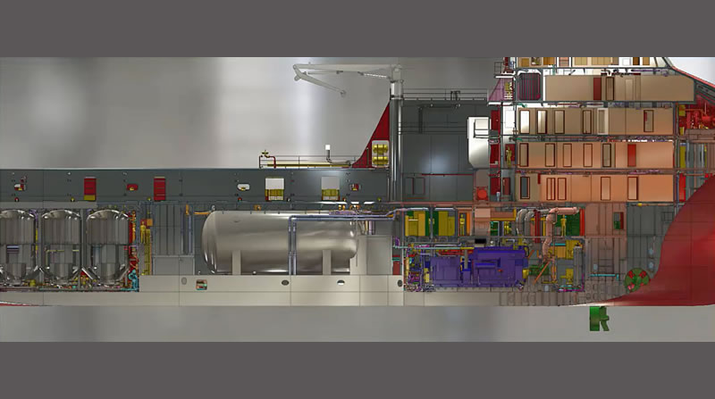
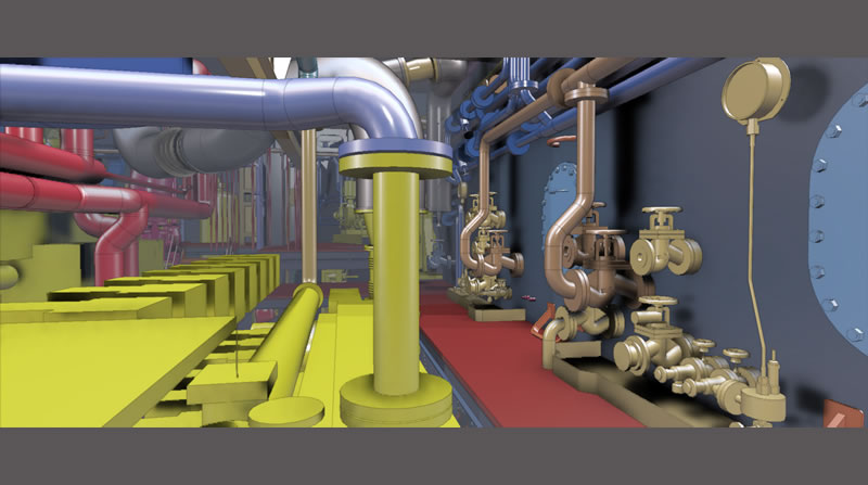
The CADMATIC Outfitting Design module is an integrated, database-driven design module that provides powerful tools for 3D layout- piping-, HVAC-, electrical- and outfitting structural design of ship and offshore projects. It also automatically produces information for production, installation and materials’ ordering, such as layout, isos and spool drawings, duct spools, electrical installation information, support sketches and many others.
- Advanced 3D viewing technique and model database structure keep the design model extremely light and user friendly even in the biggest and most complicated vessels or offshore models
- Specification-driven modeling of pipes and cable trays ensures that the correct materials, sizes and components are used during modeling
- Easy to modify existing models – saves a lot of time and effort
- Complete integration with CADMATIC Hull ensures that both hull and outfitting designers work in the same environment and can solve mutual questions, e.g. penetrations, in the simplest way
- Support Designer makes modelling of primary and secondary piping-, ducting- and cable tray sup-ports very easy and fast
- Component Manager allows the creation of parametric component models and new sizes can be added easily to the library
- Allows easy work process with globally distributed teams (link Co-Designer), share 3D models with eBrowser and on tablets with eGo and directly use results of design phase for Information management
CADMATIC Outfitting Design consists of our efficient modules that help your design team to create complete and accurate 3D outfitting models. The core system for outfitting design is 3D Outfitting Design, but it also includes electrical design, air duct spools and HVAC, piping supports, steel outfitting and weld management. We also have various interfaces for special software packages (link to interoperability).
Production Information
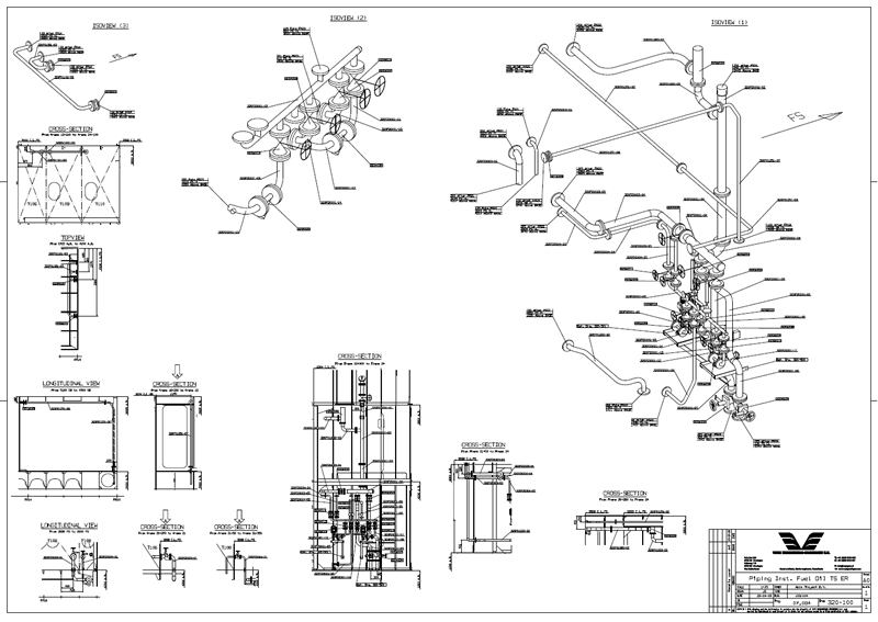
In Outfitting Production Information documentation such as layout-, piping-, HVAC- and structural drawings can be easily produced.
- Various drawing views and sections for any drawing size and format
- Drawings are updated according to changes made in the 3D model
- Revision control tool makes it easy to control changes between drawings
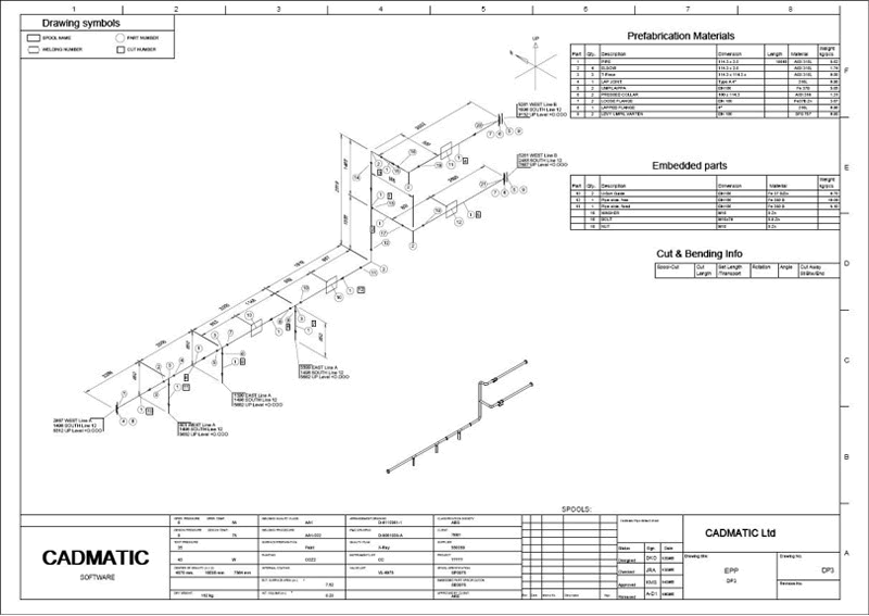
- Automatic generation of isometrics and spools, duct spools and support sketches
All kinds of drawings can be generated, including piping isometric and spool drawings, HVAC and air duct spools, foundation drawings, piping support location drawings, piping support automatic sketches, and development drawings for pipe branches etc. All these drawings can be completed in the CADMATIC drafting module e.g. fully dimensioned, annotated and then exported for example to .dwg or .pdf formats.
Marine Laser Scans
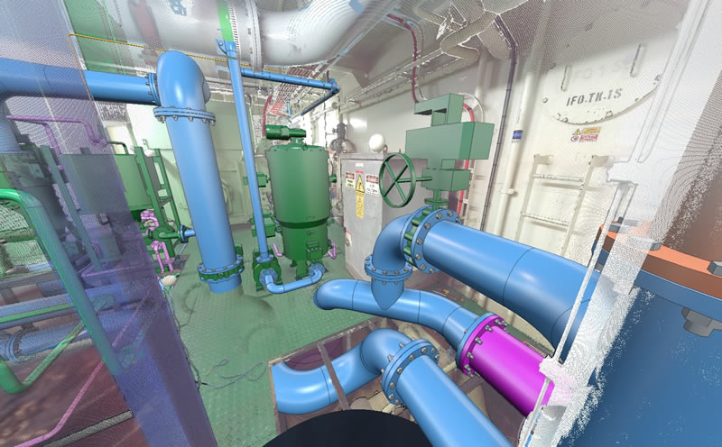
CADMATIC Laser Scan Modeller is an integrated solution for seamless use of data from laser scanners to 3D models and production data. It boosts the use of laser scanning technologies in design projects. You can utilize point clouds directly in the 3D design tool with the use of familiar design tools.
Benefit from viewing and examining an existing ship or offshore layout when sketching a new layout, use point clouds as references in measuring and fitting, while designing new items in detail or remodelling existing items. While remodelling you can directly use settings, the library and components of other CADMATIC modules for the correct attributes and materials.
- No restrictions on laser scanning equipment and formats of point clouds
- Intelligent map of scanners with annotations
- Create 3D components using specifications and library
- Model produced is fully integrated with other CADMATIC modules, including automatic ISO and BOM generation, project review in eBrowser and integration with eShare Information Management
- Reduce time for surveys, operational down time on board, and the need for on-site trips
- Fewer unknowns and assumptions regarding existing layout, reduction in re-work due to instant availability of accurate dimensions and spatial geometries
- Scope of changes can be estimated quickly
- Lack of as-built electronic documentation available from the owner/operator is no longer a need of concern
Interoperability
CADMATIC has been designed to be as open as possible to allow cooperation with different technology suppliers. We have developed an open database and implemented numerous interoperability functions.
- Import and export 2D views and 2D drawings from and to other drafting systems such as AutoCAD®, according to the AutoCAD® DXF and DWG formats, and NAPA Steel.
- Export 3D hull geometry to other 3D systems according to AutoCAD®; DXF and DWG, IGES, SAT and STEP formats.
- Convert the 3D Hull model into AutoCAD® 3D workspace for further processing. A Hull ARX plug-in module is available for translating the 3D hull model into native AutoCAD format.
- Transfer a (complete) NAPA Steel model to the CADMATIC 3D hull database. This can be done with the NAPA Steel Import module. The existing topology in the NAPA Steel model is fully preserved and adopted by the CADMATIC database. Once the model is transferred it can be used for further de-tailed engineering as if it was created with CADMATIC Hull.
- Export and import of 2D drawings from/to CADMATIC is an intelligent module for *.dwg, *.dxf, *.dwf, *.pdf and *.svg formats
- Import and export of AutoCAD® 3D models with the 3D eXchanger for AutoCAD®
- Converters for generating CADMATIC eBrowser models and CADMATIC 3DD files from PDS®, PDMS®, Smart3D® or Polytrans by Okino® models
- Conversion services to convert 3D intelligent models in PDS®, PDMS® and other formats into CADMATIC intelligent models (including the entire parametric model and attribute values).
- Import files from 3D laser scanning system into CADMATIC Outfitting
AutoCAD®, PDS®, PDMS®, Smart3D®, Okino®, SmartPlant® are registered trademarks. Any other product or brand names mentioned may be registered trademarks or trademarks of their respective owners.
Distributed Design (Marine)
CADMATIC offers an extremely robust yet resource-friendly project distribution system. It enables users to work simultaneously on the same project. This distribution system suits both large multinational operators and smaller companies and is called the CADMATIC Co-Designer.
Our Distribution design solution is based on a smart database-centric client server system that efficiently stores 3D ship models, documents and component libraries in master and replica databases hosted by a database server system. Distributing ship design work globally or adding new design teams to a project can accomplished with ease.
Ensuring the integrity and security of project data at all times receives the utmost priority in the CADMATIC Distributed Design system. In globally distributed projects data is updated at set intervals between remote design sites via an online network such as the internet, or by simply exchanging the file in an email attachment. Designers can rest assured that the automatic replication system takes care of data synchronization, thereby ensuring that no design hours are wasted due to incorrect information.
Hull Viewer
The CADMATIC Hull Viewer is a unique tool for fast 3D hull model inspection with fly trough, orbit and spinning visualization.
The user can query the model for structural details like material, thickness, weights, size, logistics etc. One-click “filter” buttons can be used to detect anomalies in hull structural thickness, material and orientation. Advanced color and lighting features are available to create photo realistic images of the ship, which can be stored in postscript, bmp or pdf format for publication purposes.
You need to register first, before you are forwarded to the download page! This provides us with Hull Viewer user information and allows us to send you Hull Viewer updates.
System requirements: Windows 7, Windows 8+
Weld manager and welds traceability
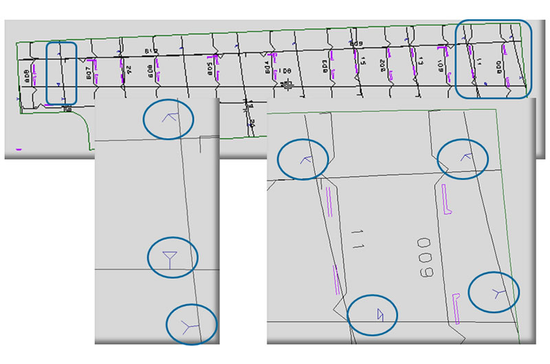
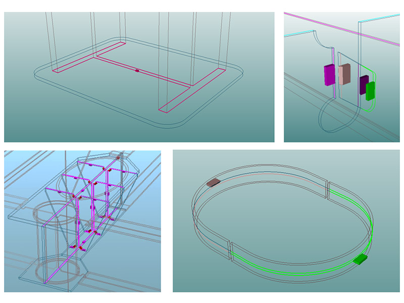
Weld Manager is an interactive tool for visualizing, modifying, organizing and exporting weld data. The tool is created to help production managers integrate welding processes into the work breakdown structure, provide detailed instructions to welders during construction and trace the status of welds throughout the entire life cycles of projects.
- Generating bevels and welds automatically, with the possibility of manual editing where necessary, while taking into account every structural part including cutouts, notches, corner holes and end types
- Visualizing and assigning welds within the work breakdown structure
- Defining work packages, estimating workloads and costs for production
- Generating automatically labeled drawings and Excel reports for weld traceability and tracking the status of welds and inspection data related to Hull or Outfitting objects in Information management solutions, also on site to assign status information of welds






Reviews
There are no reviews yet.