


Description
- Inspect parts
- Build
- Analyze data
- Report
- Reverse design
- Interface with virtually any type of portable metrology instrument
- Automate complex operations to improve measurement and inspection efficiencies.
- Address a broad spectrum of problems ranging from simple to complex
- Save time, money, effort, and ultimately improve productivity
- Establish ROI and accomplish goals that were previously impossible.
Since its inception, SA has been involved in innovative, cutting-edge applications in almost every industry involving large-scale manufacturing. SA adopters include leading manufacturers around the globe in the aerospace, shipbuilding, energy, satellite, and automotive industries.
Ever improving, SA is under continuous development to further meet customer needs and goals. Interested in learning what’s new with SA?
Videos
Introduction to SA
Basic Inspection with the Instrument Toolbar in SA
CAD Management Tools
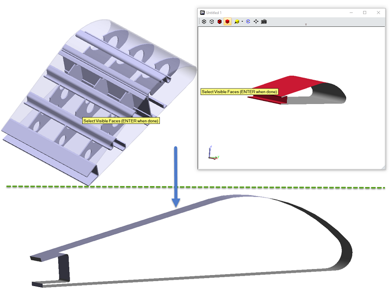
A new tool was added to remove unnecessary surface faces and reduce job file sizes: Edit > Remove Hidden Surface Faces.
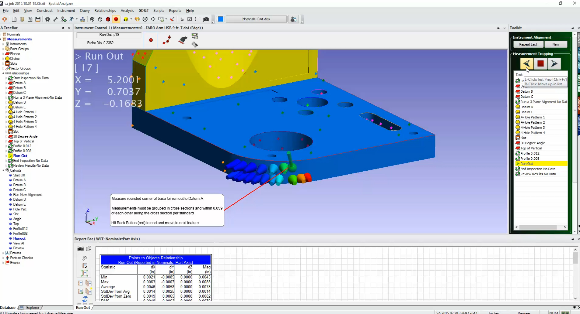
SA Toolkit Enhancements
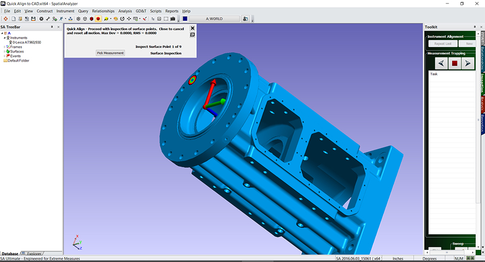
RPS Alignment Added
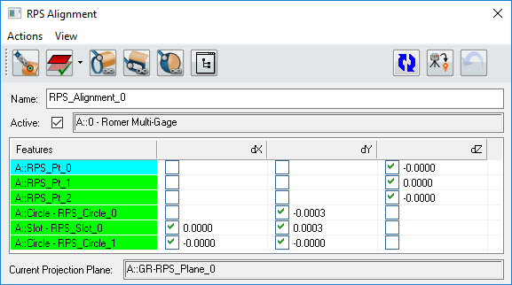
A new Reference Points System (RPS) alignment tool has been added to SA. This new alignment provides the means to control the influence of points or point reducible features on the alignment along a selectable number of axes. For example, you may want to measure points that are on different planes and use those to align the part along the Z axis, or use a circle to align the part in X and Y.
Saved Alignment in the Tree
The RPS alignment introduces the idea of a saved alignment in the tree. Doing so provides the ability to reopen, verify, and potentially re-apply alignments at any time during the measurement process. Events are still created in the tree when an additional alignment is applied.
Improved Slot Detection from CAD
The ability to extract slots from CAD has been improved including the top verses bottom selection.
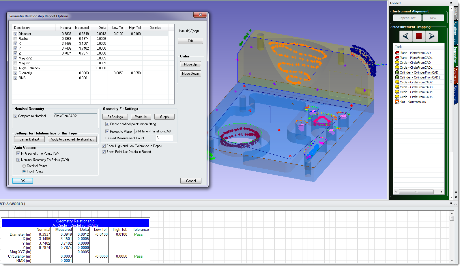
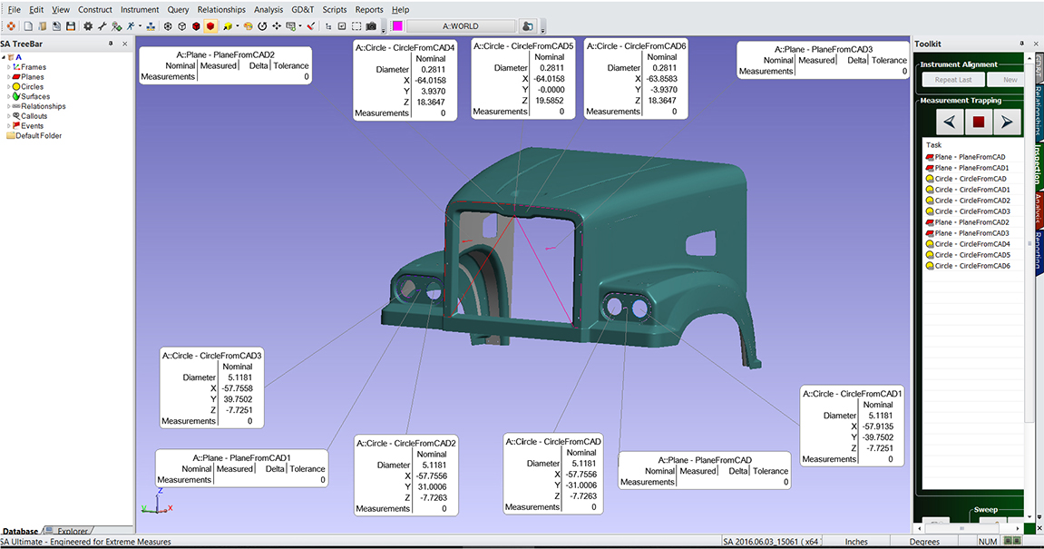
Detect Nominals by Proximity
A new tool has been added to easily detect nominal geometry from a CAD model once aligned, saving the need to manually select those nominal features. Relationships>Geometry Comparison> Detect Nominals by Proximity.
Added a Utilities row to the Relationship Tab of the SA Toolkit
This row includes three very useful functions that were previously buried deep within the Relationship menu. They include:
- Detect Nominals by Proximity. This allows you to measure features, align to a CAD model, and detect/extract the nominal geometry from that CAD within a proximity to the measured
features. - Select Nominal Geometries. Which provides an option to build geometry relationships from constructed or imported nominal geometry.
- Auto Filter to Nominal. A new tool ideal for feature extraction from a point cloud once aligned to a CAD model.

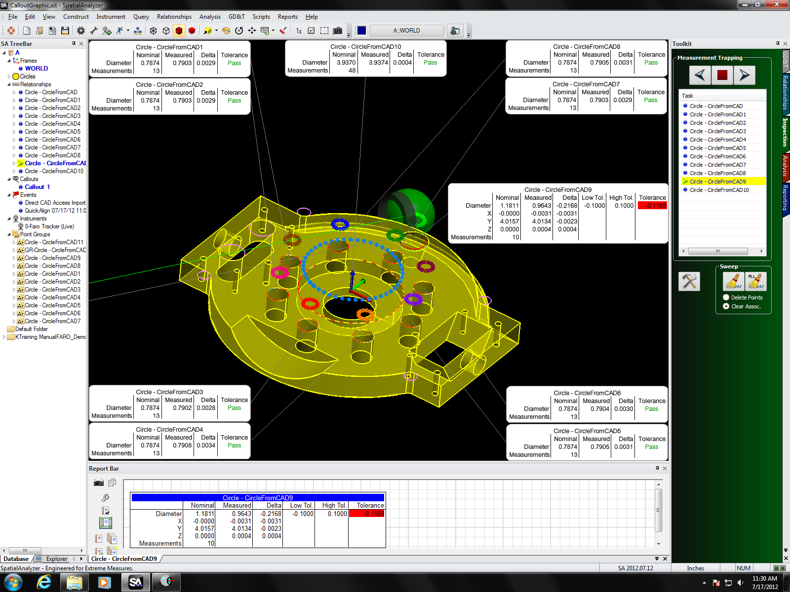
Point Cloud Operations
Live Feature Extraction
An on-the-fly auto-filtering option was added to extract cloud data as compared to nominal relationships that are built from a CAD model. This live processing makes it easy to identify and extract features from a cloud based upon their proximity to a CAD model.
Voxel Clouds
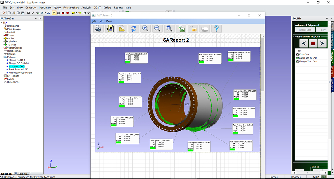
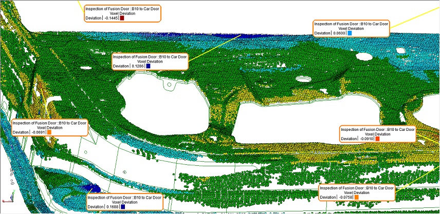
A new display mode for point clouds has been added called a Voxelized Cloud. It provides the ability to display only a single colored dot (or blotch) for each volume of a specified size. The measured cloud point closest to the average for the entire voxel or computation volume will be displayed, and the size of the voxels can be recomputed at any time. This provides a convenient way to display a uniform distribution of cloud data. When tied to a CAD model or other object by using a cloud to CAD relationship, these voxel clouds can be colorized to easily display deviation statistics.

A new voxel callout has also been added to identify the deviations in a region.
Several additional cloud deviation surface analysis displays are available to help explore surface and measurement variation.
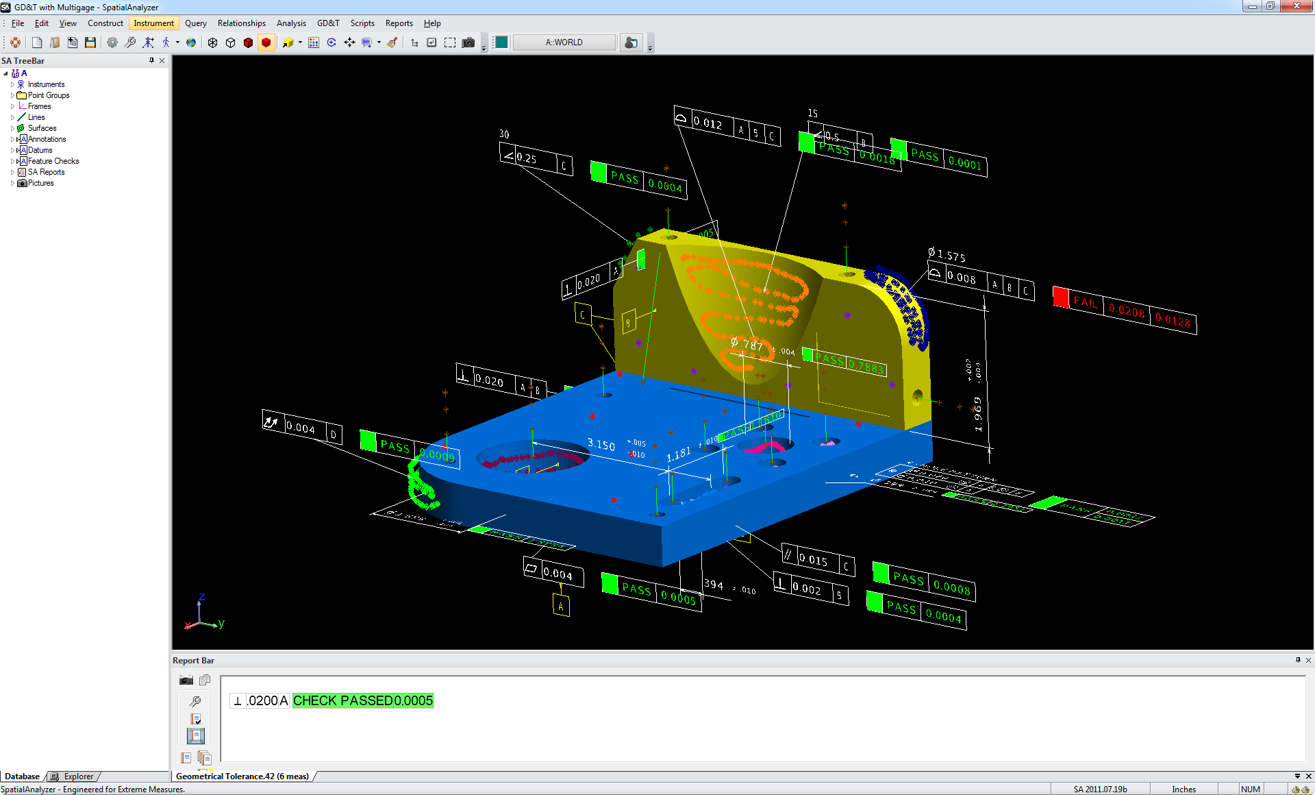
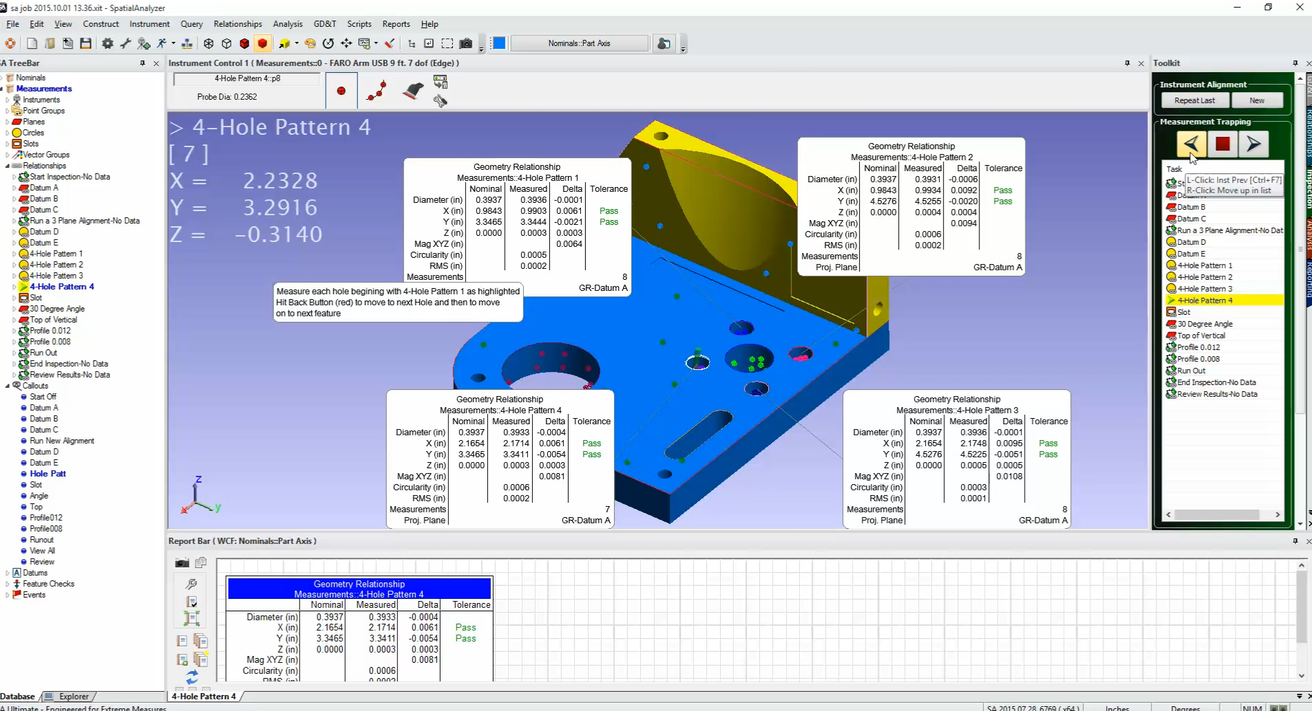
GD&T Improvements
GD&T Status Icons added:
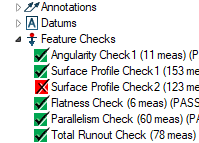
Status Icons have been added to GD&T feature checks to provide a quick and easy way to identify the status of checks in both the tree and the Inspection Tab of the SA Toolkit.
Imported Annotations Repair Function:
CAD annotations are originally imported with the leader lines and layout designed in the CAD package. However, the links to the correct CAD faces are sometimes lost. In this version, we have added a right-click repair function that allows you to rebuild the annotation link with the CAD without losing CAD leader lines or layout elements.
Object Associations are easier to control:
The CAD face associations can now be easily modified. When editing face associations in an annotation, the faces are highlighted and individual faces can be turned, included, or excluded from the list through graphical selection.
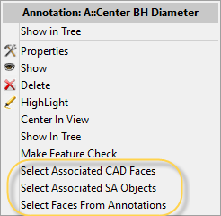
Three new options have been added to the Annotation right-click menu allowing easy feature association. Selection from other annotations will automatically link the annotation to the same selected features.
Reporting Improvements
Dimension Leader Line Improvements
Point to Point and Diameter dimensions can now be positioned more effectively, and greater leader line control has been added.
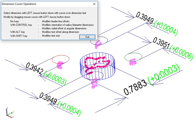
2D dimension display can now be displayed as part of Point to Point dimensions, in addition to the already existing single component definition.
Callouts are now linked to Clipping Planes
When a clipping plane is active, the callouts linked to points behind the clipping plane are now automatically hidden from view.
Instrument Updates
Laser Tracker Improvements
The ability to use proximity triggers with the T-Scan and LAS scanners has been added. This provides the ability to capture exact point location measurements very quickly and is already available for arm scanners.
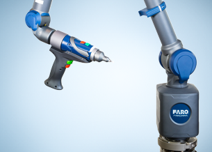
PCMM Arms
Support for the Faro QuantumS and Quantum M arms including a new graphics model has been added.
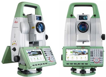
Total Station Improvements
This version includes new TS 16 Interface with support for wireless communication and PhotoNideo controls.
Photogrammetry Improvements
- Dynamic Reference Controls for the AICON Movelnspect system including MP operational checks to set them and a Create New Dynamic Reference command have been added.
- MP support for GSI V-Stars interface configuration has been added. This includes a much expanded set of Instrument Operational Check string commands.
Measurement Plan
MP Editor Enhancements:
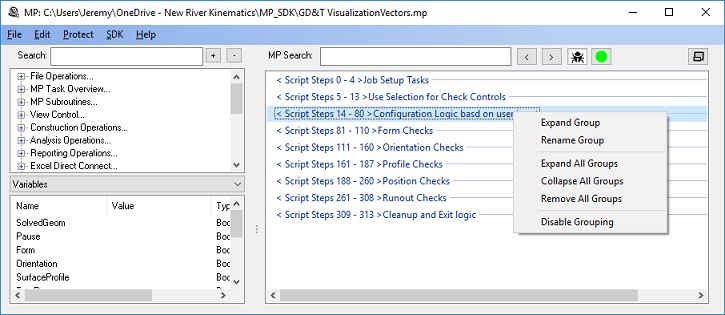
Added grouping and section headers to scripts which provides the ability to easily separate and navigate a large MP.
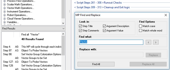
MP Editor Find and Replace Functions Added:
A new Find (Ctr+F) and Replace (Ctr+H) function has been added to the MP editor to make it easier to find steps of interest and edit existing entry fields. This includes both a find editor and a navigation panel for easy navigation between the steps identified.
New MP command were added:
- Get Feature Check Reporting Options. Returns the current reporting options set for the selected feature check.
- Set Feature Check Reporting Options. Provides the means to adjust the reporting options for the specified feature check.
- Invert Transform. Implemented so that T_ input* T inverted = T identity.
- Construct Surface by Projecting Points. Like the existing construction menu command, this step builds surfaces from the projection of points and provides an easy way to identify what surfaces are needed from a large model.
- Construct Points By Projecting Points On Mesh Along Direction. Builds points at the projection point on a mesh.
- Construct Frames By Projecting Frames On Mesh Along Frame Direction. Builds frames with origins at the contact point on a mesh using the reference frame Z-axis as a direction.
- Construct Frames By Projecting Frames On Mesh Along Reference Direction. Builds frames with origin shifted to the contact point on a mesh.
- Construct Points on Curves Using Max Chordal Deviation. Builds points on a b-spline providing density control based upon rate of curvature in the reference spline.
- Create New Dynamic Reference. Added for Movelnspect systems, this command allows you to define a new dynamic reference from selected points.

Reviews
There are no reviews yet.